🚗 CAN Bus
CAN (Controller Area Network) is a robust serial communication protocol widely used in automotive, industrial, and embedded systems. It allows multiple nodes to communicate over a shared two-wire bus without a central host controller.
Note
Good course: Understanding the CAN FD Protocol
Overview
Physical Layer
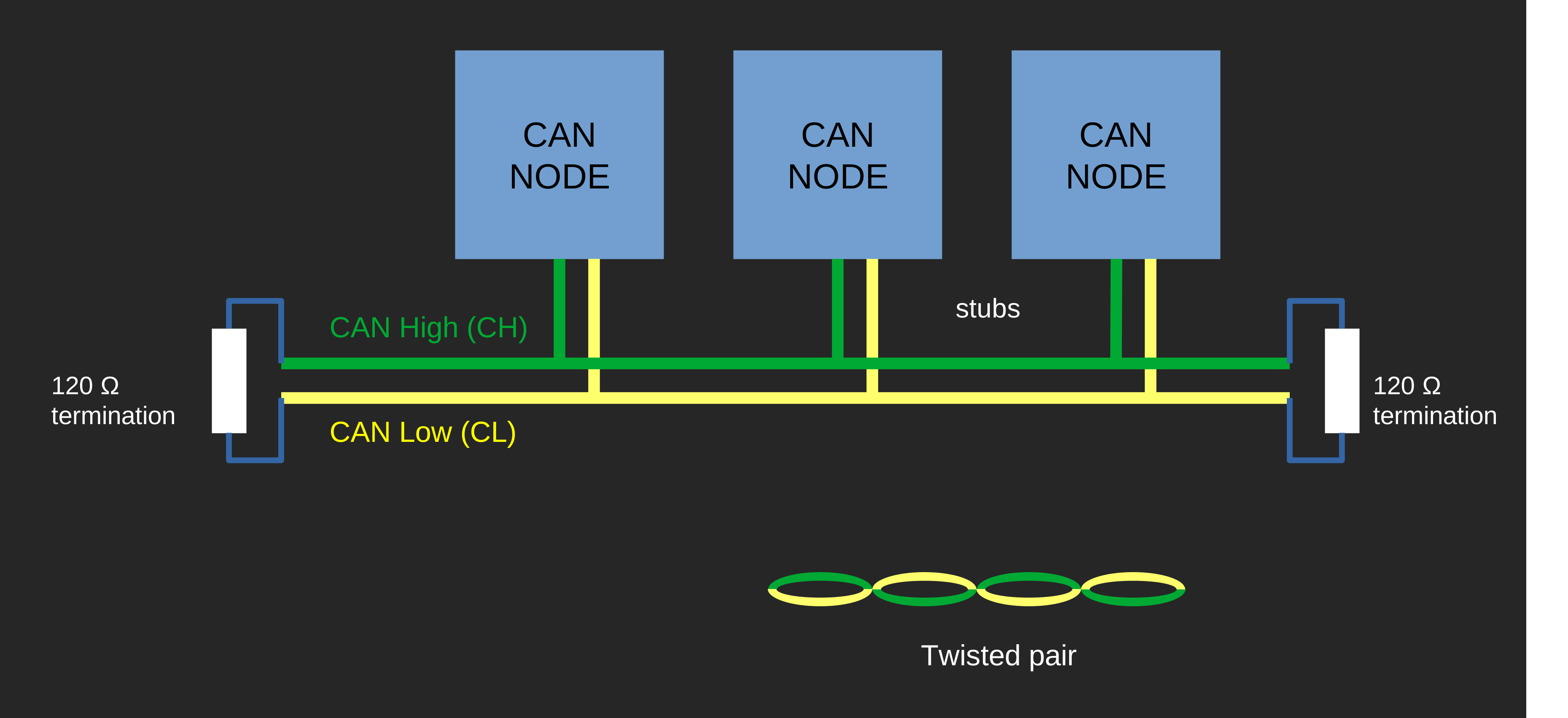
The bus uses two wires — CANH and CANL — operating differentially. The bus is terminated at both ends with 120 Ω resistors to prevent signal reflections.
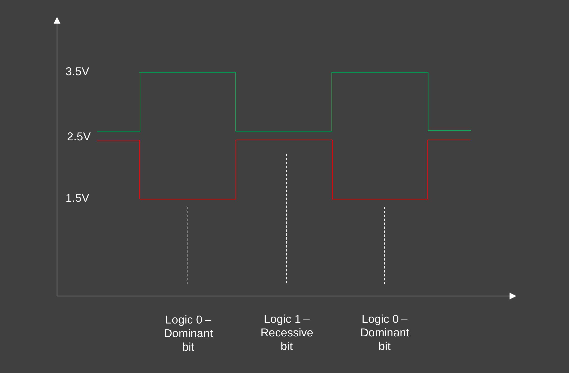
Two logic states exist on the bus:
Dominant — logical 0 (CANH driven high, CANL driven low)
Recessive — logical 1 (both wires at the same voltage)
When nodes drive conflicting states simultaneously, dominant wins. This is the basis for non-destructive bus arbitration.
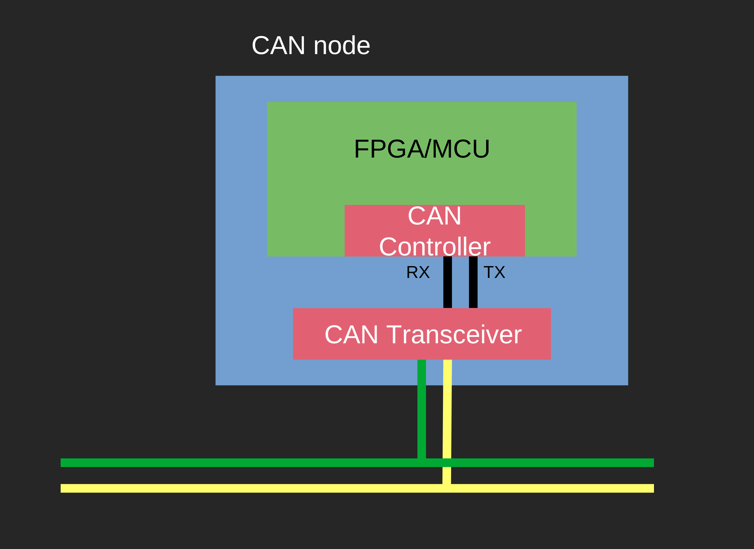
There are two layers in the CAN protocol stack:
CAN Transceiver — handles the physical layer (drives and reads the differential bus voltages)
CAN Controller — handles the data link layer (framing, arbitration, error detection)
Each node on the bus contains a transceiver and a controller:
Node Communication
CAN uses CSMA/CD+CR (Carrier Sense Multiple Access with Collision Detection and Collision Resolution):
Carrier Sense (CS) — nodes monitor the bus and wait for it to be idle before transmitting
Multiple Access (MA) — when the bus is idle, every node has an equal opportunity to transmit
Collision Detection (CD) — nodes can begin transmitting simultaneously; this is detected by all nodes
Collision Resolution (CR) — when a collision occurs it is resolved non-destructively — no messages are lost
The resolution mechanism relies on the dominant/recessive logic: a node that writes a recessive bit but reads back dominant has lost arbitration and immediately backs off. The winning node’s frame continues uninterrupted.
Frame Types
CAN defines four frame types:
Data Frame — carries payload data from a transmitter to one or more receivers
Remote Frame — requests a data frame with a specific identifier from another node
Error Frame — signals that an error has been detected; all nodes discard the current frame
Overload Frame — signals that a receiving node needs more processing time before the next data or remote frame
Arbitration
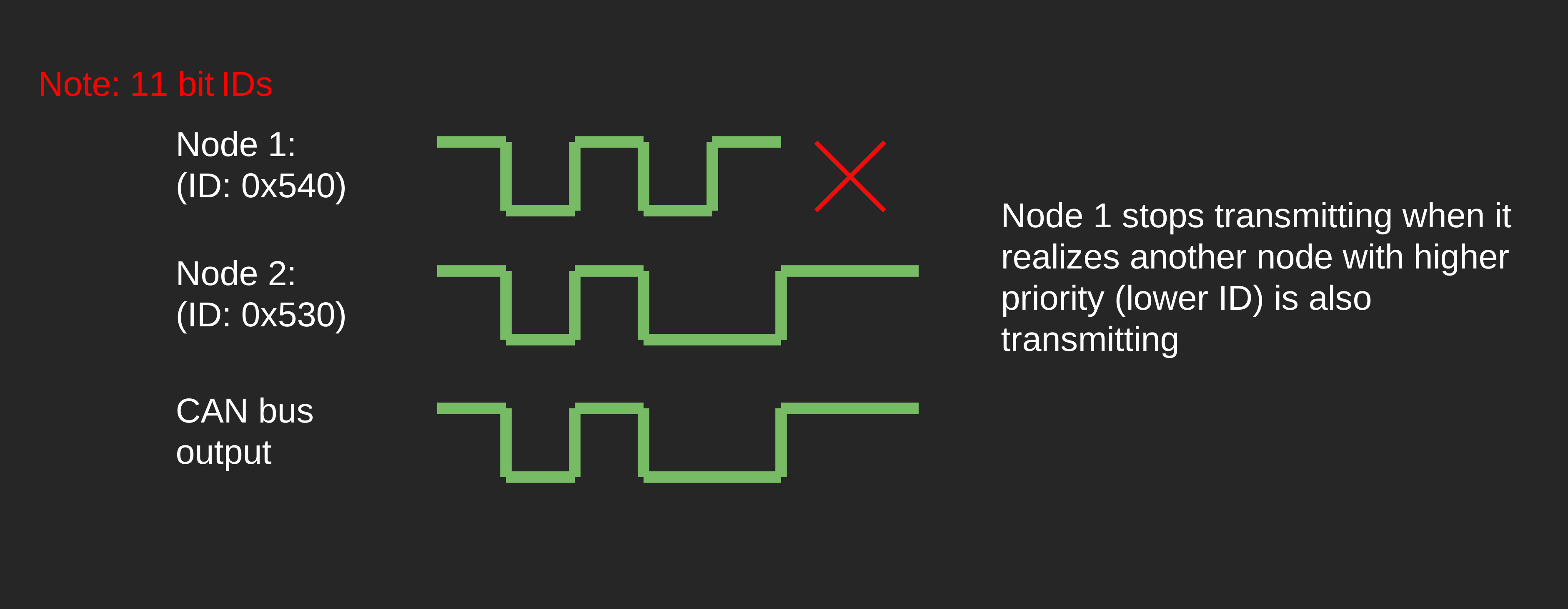
CAN uses identifier-based arbitration, not addressing. Every frame carries an identifier. Lower identifier values have higher priority — because a lower ID has more leading dominant bits and will win arbitration.
When two nodes begin transmitting simultaneously, each node monitors the bus while it transmits. As long as what it writes matches what it reads, it continues. The moment a node writes a recessive bit but reads a dominant bit back, it loses arbitration, stops transmitting immediately, and waits for the bus to become free.
The winning node never even knows a collision occurred — transmission continues uninterrupted.
Note
CAN controllers have filter and mask registers so a node only receives frames whose identifiers match a configured pattern, ignoring everything else on the bus.
Bit Stuffing
To ensure regular transitions on the bus (needed for clock synchronisation), CAN inserts a stuff bit after every 5 consecutive bits of the same polarity. Receivers strip these extra bits automatically.
Stuff bits apply to the SOF, arbitration, control, data, and CRC fields. They do not apply to the CRC delimiter, ACK field, or end of frame.
Frame Structure (Classical CAN)
A standard CAN data frame (11-bit identifier) has the following structure:
Field |
Size |
Description |
|---|---|---|
Start of Frame (SOF) |
1 bit |
Single dominant bit — signals the start of a frame and synchronises all nodes. |
Identifier |
11 bits |
Frame identifier. Lower value = higher priority. |
RTR |
1 bit |
Remote Transmission Request. Dominant = data frame. Recessive = remote frame (requests data from another node). |
IDE |
1 bit |
Identifier Extension. Dominant = standard 11-bit frame. Recessive = extended 29-bit frame. |
r0 |
1 bit |
Reserved bit, transmitted dominant. |
DLC |
4 bits |
Data Length Code — number of bytes in the data field (0–8). |
Data Field |
0–64 bits |
Payload (0–8 bytes as specified by DLC). |
CRC |
15 bits |
Cyclic redundancy check covering SOF, arbitration, control, and data fields. |
CRC Delimiter |
1 bit |
Recessive bit — gives receivers time to process the CRC before the ACK slot. |
ACK Slot |
1 bit |
Transmitter sends recessive. Any receiver that passed the CRC check writes dominant here — confirming at least one node received the frame correctly. |
ACK Delimiter |
1 bit |
Recessive bit. |
End of Frame (EOF) |
7 bits |
Seven recessive bits — marks the end of the frame. |
Intermission |
3 bits |
Three recessive bits — minimum bus-idle time before the next frame. |
CAN FD
CAN FD (Flexible Data-rate) extends classical CAN with two improvements:
Higher payload — up to 64 bytes (vs. 8 in classical CAN)
Faster data phase — the data and CRC fields are transmitted at a higher bit rate than the arbitration phase
The control field adds an FDF (FD Frame) bit to distinguish CAN FD frames from classical CAN frames:
FDF dominant — classical CAN frame
FDF recessive — CAN FD frame
CAN FD also replaces the 15-bit CRC with a longer CRC (17 or 21 bits depending on payload size) for improved error detection.
Synchronization
CAN uses asynchronous communication — there is no shared clock between nodes. Each node must synchronise its internal clock to the received bit stream.
Synchronisation happens on recessive-to-dominant transitions, most importantly the SOF bit at the start of each frame, and at other transitions throughout the frame.
To prevent long stretches without a transition (which would cause clocks to drift), CAN inserts stuff bits after every 5 consecutive bits of the same polarity. Receivers strip these automatically. A violation of this rule — 6 or more consecutive bits of the same polarity — is treated as a stuff error.
Error Handling
Error Detection
CAN defines five error types:
Bit error — the transmitter monitors the bus and finds a bit different from what it sent (excluding arbitration and ACK phases)
Stuff error — six or more consecutive bits of the same polarity detected (violates the stuffing rule)
CRC error — receiver’s calculated CRC does not match the transmitted CRC
Form error — a fixed-format field (CRC delimiter, ACK delimiter, EOF) contains an invalid bit
Acknowledgement error — transmitter sees no dominant bit in the ACK slot (no receiver confirmed reception)
Error Flags
When a node detects an error, it immediately aborts the current frame by transmitting an error flag. This corrupts the frame for all other nodes, which then also send error flags.
There are two types of error flag:
Active error flag — 6 consecutive dominant bits (violates bit stuffing, making the error visible to all nodes)
Passive error flag — 6 consecutive recessive bits (does not disrupt other nodes)
The error flag is followed by an error delimiter — 8 recessive bits.
Error Confinement
Each node maintains two counters:
Transmit Error Counter (TEC)
Receive Error Counter (REC)
Counters are incremented on errors and decremented on successful operations. The exact increments depend on the error type, but as a rule: errors increment by +8 for the transmitter and +1 for the receiver; a successful frame decrements by 1.
Based on these counters, each node operates in one of three states:
State |
Counter threshold |
Behaviour |
|---|---|---|
Error Active |
TEC < 128 and REC < 128 |
Normal operation. Sends active error flags (6 dominant bits) on error detection. |
Error Passive |
TEC ≥ 128 or REC ≥ 128 |
Still participates on the bus, but sends passive error flags (6 recessive bits) — cannot disturb other nodes. |
Bus-Off |
TEC ≥ 256 |
Node disconnects from the bus entirely — cannot transmit or receive. |

Recovery from Bus-Off
A Bus-Off node can request recovery. The node monitors the bus for 128 occurrences of 11 consecutive recessive bits before re-entering Error Active state.
CAN Database
A CAN database (commonly a .dbc file) lets you define your network in one place — node names, message identifiers, signal names, scaling, units, and more. Once designed, the database can be exported and used with tooling such as:
Loading into a CAN bus analyser to decode raw traffic with meaningful labels
Code generation for embedded targets
Tools for creating and editing CAN databases:
Kvaser Database Editor — desktop tool
CSS Electronics DBC Editor — online editor